Morgan Out Island 41 Pedestal Upgrade
Morgan Out Island 41 Pedestal Upgrade

When we first bought our Morgan Out Island in 2015, the Previous owner had started on a rudimentary console to hold sailing instruments that surrounded the existing binnacle compass. As it was far from complete we discarded it and built a ply wood “pod” with the intention of housing the existing Raymarine ST60 trio of Speed, Depth and wind instruments. Added to that I purchased a Garmin Echomap 7 inch plotter to give me some navigational data

The Design
The concept for the new pod was to condense the entire system into a small a package as possible while still improving overall usability. The old pod had speed, depth, wind, autopilot, VHF remote mic and windlass controls in the pod. In front of the pod was an original Morgan carded Danforth Constellation compass. I wanted to retain the compass as it was unique to the boat, but also to make the compass more usable and take up less space. My compass dome was crazed with age (45 years) so it was sent off to Viking Optics in Maine to have it rebuilt and converted from binnacle to deck mount. The compass came back looking like brand new. After that I was committed to the project.

The modification to the pedestal started out taking a number of measurements from the existing pedestal to establish the width and depth of the pedestal, making notes on any thing that might be an obstruction or issue later . For example, on the front side of the pedestal there is an access door that needs to be accounted for so that the new Pod doesn’t interfere with the action of the door. On the starboard side of the pedestal the shift/throttle lever needs to be accessible to operate Then an evening working with CAD (Cardboard Aided Design). The initial step here is to create the “box” to represent the top of the pedestal, then print out the install templates for each of the items i wanted to install and lay them out in the way you want around the box. Thankfully all the install templates I used had cutting measurements in mm so I was able to print out and measure until i had true to life templates (more on that later) and then work on a layout that worked for me. Once I had a rough idea of the layout I cut the cardboard “face” to fit as a rectangle, with a cutaway for the box. After that I had to determine the rake to the face. In the end I settled on 15 degrees. From there the next principle dimension was the depth needed behind the center section in order for he MFD and its cable connection to fit. Raymarine wants a bit over 6 inches behind the face of the MFD for the cabling (with the right angle connector) to fit. I think this is a bit over conservative as mine seems to fit with at least 3/4” space between the connector and the back of the pod. With that dimension set and a 2 inch width to the top and sides it was a simple matter to fill in the space later with foam and shape it.
The plug
Once the CAD excercise was done and the principle dimensions established it was time to build the plug from which I was going to pull the molds. To do this I used MDF as its readily available, cheap and machines well. The back side of the plug I made of XPS foam (again cheap) and glassed it with 2 layers of 4oz cloth and epoxy both to seal and protect the foam from the next part of the process. The MDF was also sealed with epoxy. After that it was wet sanded to remove any bubbles and defects, then 6 coats of wax were applied and buffed.

The Mold
Because of the shape of the Plug I realized that a 2 piece mold was not going to work as the forward face of the lower box and the top of the pod were angled in ways that would have locked the mold to the plug and removal would have been impossible without destroying the plug (I didn’t want to destroy the plug just in case I had to remake a mold section) the lower half of the mould was made in 2 pieces to be bolted together later when it came time to manufacture the part.

To make The mold flanges I hot glued some 1/8” hardboard to the sides of the mold where I wanted the parting line to be (If I were to do this again, I would use 1/4” just for the added rigidity it would give. The hardboard parting flange was needed in order to create the top mold and as a face of the forward lower mold. Once I got to the mold for the back part, I just heavily waxed the flanges that resulted from making the first 2 piece and created the final mold piece using the existing flanges. Once all the mold pieces were made but still on the plug, I drilled for locating bolts so that the final alignment would be guaranteed. In the second picture to the right, you can see the lower mold 2 pieces bolted together and the upper half mold.

Producing the part
Once the molds were done, it was an evening of applying wax and buffing the 2 molds. There ended up being a couple of defects in each mold, but some modelling clay took care of that. Each part got 2 layers of white gelcoat rolled into it a few hours apart. The next day i was able to produce the part. For both the top and bottom I used the following layup schedule:

This left me with a part that was a little over 1/4” thick and as there were 2 layers of 1708 incorporated , I feel stronger than just a mat and roving part. The original pedestal ended up being a bit all over the place for thickness. The face with the helm pump bolted to is was almost 1/2” thick where the forward side was as thin as 1/8”.
Assembling the part
Once the 2 halves had been produced, I cut the excess glass from the molding process off while the parts were stil in the mold, in the end this wasn’t necessary as the gelcoat marked the boarder to cut as all the excess had no gelcoat! Pictured to the right are the 2 pieces after trimming. The next step in the process was to glue the two halves together with thickened epoxy. Once the Epoxy has cured it was time to grind the joint to make room for 3 layers of 6oz fibreglass tape to reinforce the joint. I ground and glassed the sides first to ensure that there was no movement in the parts. Once the whole joint was glassed I faired the joint using epoxy thickened with some cabosil and microballons.

Laying out the instruments
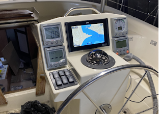
Once the part was fully glassed and faired I laid out the instrument mounting holes using the templates that were previously used to establish the size of the pod. Here you can see the 4 ST 60 instruments in their final locations, the Switch panel to the left and the rebuilt compass mocked up. Time to take this part to the boat and get it installed!!

Cutting the Pedestal
Now for the most unnerving part of this upgrade. Cutting the top off the pedestal. Lest start with the old setup. First step in my case was to cut off the old pod, taking the pedestal back to its original look. There are 2 marks here on the Pedestal. The Cut line just below where the pedestal starts to taper to the top rounded section. The dotted line 2 inches below the cut line is where the taper I ground ends.

Here you can see the pedestal with the top cut off. There’s no going back now, we’re committed to the modification now! You can see here the plywood used to further strengthen the pedestal assembly where the Hynautic hydraulic helm is. Its worth noting that my pedestal has already been modified once in the past. There used to be a recess for engine controls and switches, When I repowered a number of years ago I moved the control panel to the starboard coaming as that made viewing the gauges far easier, so that recess was cut out and a replacement panel glassed in and faired. In the picture to the right you can also see the remnants of the struts that held my previous pod. Now is the time to clean up all of this, Cut that piece of plywood flush with the rest of the cut and if you need to do any wiring now is the time to prep for it.

Installing the new pod
To install the nav pod, first we need to grind a taper in the top 2 inches of the pedestal. Once that is done we need to create a matching taper in the edge of the pod. To do that, cut the bottom 3/8” off the pod (this cuts of the bottom that was part of the molding) Once the bottom is cut off the new pod, grind the taper. I recommend doing all outside if possible and not under a cover. The grinding dust gets EVERYWHERE!!!! With the 2 tapers and the original cut line, the top of the compass mount should be 38 inches above the cockpit sole. If you want this lower just cut the pedestal lower, just be aware of the opening on the front side of the pedestal and the mounting area for the hydraulic helm on the aft side.

Once the pedestal and pod are ready to go, mix up some thickened epoxy (cabosil for me as it creates a very hard strong gap filling mix.) and install the pod mount onto theold pedestal base. Check your measurements to ensure that the compass mount is even side to side and fore and aft.
Once the epoxy has cured, grind a bevel in the joint and then lay at least 3 layers of 6oz 2 inch wide fibreglass tape to reinforce the joint. A bit of peel-ply here makes the fairing process much simpler. When you get to fairing, you’ll be spreading the fairing putty about 6 inches wide and then spend time blending the new pod into the pedestal base, fairing, fairing and more fairing. The final steps included 3 coats of primer (sanding between each application) for Primer I used Interlux Pre-Kote modified with Petit’s Performance enhancer. Petit’s product turns single part polyurethane paints into a semi 2-part system. Works very well. Top coat here was 3 coats in Interlux Brightsides Hatteras Off-White 1990 also modified with Petit Performance Enhancer.

The final step in the assembly was to install all the electrical and electronics, install a piece of plastic cable ducting in the pedestal to manage all the wiring and revarnish the door for the front.

Comments
Post a Comment